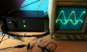
Someone called saying he had a Valhalla power supply in his Linn Sondek LP12 turntable which was starting to fail, and rather than repair it he would like try what’s known as a “DIY Armageddon” outboard power supply. While a bit doubtful at first, we agreed this would be an interesting project and that I would take it on. The manufacturers (Linn) do make an outboard ‘Armageddon’ power supply, but theirs is £1200 and this one is £250. This project involved many hours of research, much of it sifting through audio forums related to previous builds, separating the armchair theorists from those with actual experience and the ability to express their findings impartially.
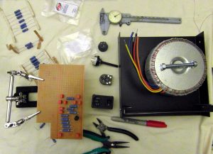
Let’s make a start. There is much debate about the transformer but the Nuvotem Talema 500VA 55-0-55v (available from RS) is a common choice, and is similar to the one Naim use in their design. As the transformer is the largest item to put in the box, we’ll start with that.
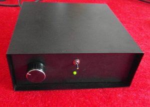
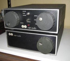
Speaking of boxes, the customer sent a photo of his existing kit, so I looked for a case which was similar. The only disappointment is that I couldn’t find a round knob for the front panel which matched the existing Naim kit (well, not for sensible money anyway!), so I asked the customer to choose something
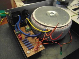
A few photos taken during the build.
This one shows the LED wiring going around the transformer [to the red LED on the rear panel, out of view here], but in the final design this was suspended away from the casing. The final design also contains a soft-start resistor as I found that the toroidal transformer was noisy and was blowing fuses when there was no start-up current limiting. Normally you would bypass the soft start component once the transformer is powered up, but the secondary load is so small that there’s no need to
For anyone thinking of building one, I should say that the blue resistors you can see range from 3.3k to 8.2k, and are wired to a 5-position rotary switch on the front panel, giving outputs of approximately 60, 67, 73, 78, or 88V(rms) as measured at the motor. The idea is that you choose the lowest setting at which the turntable will work reliably, as the motor vibrations decrease with lower voltage. There’s also some dropper resistors and a bridge rectifier powering the LEDs. The front panel switch is between the secondary windings, than there’s a switch in the IEC socket/fuse too.
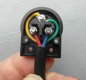 The 4-core cable I found for running to the turntable was rated for high voltages but didn’t have very good mechanical properties so I sleeved it with an expanding nylon braid casing and heatshrink tubing
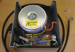 The final design, and some testing going on. The two output voltages which drive the motor are correctly phased (90 degrees difference, as per the red arrows on the oscilloscope display) but I was slightly concerned that they weren’t the same amplitude. The reason for the difference is that I’m using a resistive load to test the unit, whereas the motor has inductance too (i.e. the interaction between the output phase-shift capacitor is different). When it was time to do some testing with the actual turntable, I rigged up a temporary switch so that different capacitor values could be tried; it turns out that 0.2uF gives the same voltage on both motor windings. The other values I tried were 1.7 and 2.2uF but these gave imbalanced voltages.
It should be noted that although design and construction was to me my best abilities and with every safety feature in place, it is effectively a home made piece of equipment with no recognised approvals etc. The customer was very aware of this, was happy about it, and gave me a written disclaimer to that effect. I was pleased to hear that it has all been worth while, he said that “I have to tell you, it sounds stunning. I know there’s always the placebo effect with stuff like this, you only think you can hear the difference but there are a couple of records I know so well I can spot changes”
